T-SIM by ACCUFORM for thermoforming simulation
Blog rivolto al mondo accademico (studenti, professori) con le ultime Notizie, Tips e Tricks su SolidWorks.---------------------------------------------------------------------------------------------Bilingual Italian-english blog for the academic world (students and teachers) with the lastest SolidWorks News, Tips and tricks
mercoledì 25 febbraio 2015
lunedì 23 febbraio 2015
La continuità di curvatura e le superfici di classe A
Con l'uscita di SOLIDWORKS Industrial Design annunciata al SOLIDWORKS World 2015 a Phoenix SOLIDWORKS si appresta ad entrare ancora di più nel mondo del Design dalle forme ricercate. In questo nuovo mondo sono comuni dei termini come continuità curvatura di tipo C0,C1,C2, C3, oppure strisce di zebra.
Questo articolo del blog della CAPINC dà un approccio molto pratico all'argomento spiegando cos'è la continuità di curvatura a cosa si ispira la visualizzazione a strisce di zebra.
Un metodo molto pratico per analizzare la curvatura è l'utilizzo dei pettini di curvatura. Le immagini che seguono provengono da una presentazione di Mark Biasotti al SOLIDWORKS World 2007:
Un'altro termine spesso utilizzato nell'ambito del design è "superfici di classe A". Questo post da un'idea di cosa indichi.
A prcactical way of analizing curvature is using curvature combs. The above pictures come from a presentation at SOLIDWORKS World 2007 by Mark Biasotti.
With C0 curvature, the endpoints of the two curves meet exactly. Note that two curves that meet at any angle can still have positional continuity.
C1 is the same as positional continuity, plus the end tangents match at the common endpoint. The two curves appear to be traveling in the same direction at the join, but they may still have very different apparent “speeds” (rate of change of the direction, also called curvature).
C2 is the same as tangent continuity, plus the curvature of the two curves matches at the common endpoint. The two curves appear to have the same “speed” at the join.
C3 is the same as curvature (C2) continuity, plus the rate of change in the curvature matches between the curves.
Another term that is often used in the design field is "class A surfaces". This post gives you an idea of hat does it mean.
Questo articolo del blog della CAPINC dà un approccio molto pratico all'argomento spiegando cos'è la continuità di curvatura a cosa si ispira la visualizzazione a strisce di zebra.
Un metodo molto pratico per analizzare la curvatura è l'utilizzo dei pettini di curvatura. Le immagini che seguono provengono da una presentazione di Mark Biasotti al SOLIDWORKS World 2007:
Con curvatura di tipo C0 si intende che due superfici sono semplicemente in contatto. L'angolo tra le superfici può avere infiniti valori possibili.
Con curvatura di tipo C1 si intende che due superfici sono in tangenza, ma la loro curvatura nella zona di contatto non coincide.
Con curvatura di tipo C2 si intende che due superfici hanno la medesima curvatura nella zona di contatto.
Con curvatura di tipo C3 si intende che due superfici hanno la medesima curvatura nella zona di contatto, ma inoltre la variazione delle due curvature è la medesima. In SOLIDWORKS è possibile ottenere questo risultato andando a modificare la profondità di tangenza delle due curve finchè le due variazioni di curvatura non coincidono.
Un'altro termine spesso utilizzato nell'ambito del design è "superfici di classe A". Questo post da un'idea di cosa indichi.
Curvature continuity and class A surfaces
With the release of SOLIDWORKS Industrial Design announced at SOLIDWORKS World 2015 in Phoenix SOLIDWORKS is entering the world of design and complex shapes. In this new world there are common terms like C0,C1,C2, C3 continuity or, zebra stripes.
This post from CAPINC Blog gives a first explanation and explains what zebra stripes are inspired to.A prcactical way of analizing curvature is using curvature combs. The above pictures come from a presentation at SOLIDWORKS World 2007 by Mark Biasotti.
C1 is the same as positional continuity, plus the end tangents match at the common endpoint. The two curves appear to be traveling in the same direction at the join, but they may still have very different apparent “speeds” (rate of change of the direction, also called curvature).
C2 is the same as tangent continuity, plus the curvature of the two curves matches at the common endpoint. The two curves appear to have the same “speed” at the join.
C3 is the same as curvature (C2) continuity, plus the rate of change in the curvature matches between the curves.
Another term that is often used in the design field is "class A surfaces". This post gives you an idea of hat does it mean.
mercoledì 18 febbraio 2015
domenica 15 febbraio 2015
Che cos'è il controllo Jacobiano in SOLIDWORKS Simulation
Questo articolo dal Blog Dassault Systèmes SOLIDWORKS ci spiega che cos'è il controllo Jacobiano e come influenza le analisi di SOLIDWORKS Simulation.
What is Jacobian check in SOLIDWORKS Simulation
This post fromDassault Systèmes SOLIDWORKS blog explains what is Jacobian check and how does it influence analysis with SOLIDWORKS Simulation.
La Showroom virtuale dei prodotti progettati con SOLIDWORKS
In questo thread dei SOLIDWORKS forums "Pictures of SOLIDWORKS projects" gli utenti SOLIDWORKS da tutto il mondo postano le immagini di prodotti che progettano con SOLIDWORKS. Vi stupirà vedere la quantità di settori e la complessità dei progetti.
NOTA: per accedere al thread è necessario effettuare il login ai SOLIDWORKS forums.
A virtual showroom of products designed with SOLIDWORKS
This thread from the SOLIDWORKS forums "Pictures of SOLIDWORKS projects" show what products are being designed by SOLIDWORKS users all around the world. You'll be amazed by the complexity of the designs and by the quantity of industries involved.
NOTE: you'll need to login in order to access this forum thread
Quale hardware utilizzare per SOLIDWORKS Flow Simulation
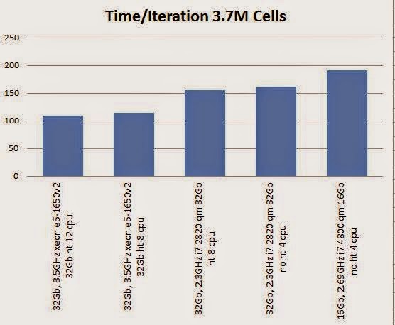
In questo interessante articolo del Blog della FISHER/UNITECH viene affrontato in maniera esaustiva l'argomento: hardware per utilizzare SOLIDWORKS Flow Simulation tenendo conto di vari fattori: quantità di RAM, tipo di CPU, tipo di disco fisso.
What hardware should you use for SOLIDWORKS Flow Simulation ?
This interesting post from FISHER/UNITECH blog shows an interesting benchmark on hardware to use for SOLIDWORKS Flow Simulation by taking into account all important components like RAM, CPU type, and hard disk type.
mercoledì 4 febbraio 2015
Parametrizzare le parti con schizzi di layout
Ecco due preziosi filmati che mostrano la tecnica degli schizzi di layout (o schizzi scheletro) per comandare la parametrizzazione del modello 3D:
How to parametrize parts with layout sketches
domenica 1 febbraio 2015
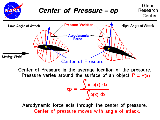
Calcolare il centro di pressione di un profilo alare con SOLIDWORKS Flow Simulation
SolidWorks - Calculate the Center of Pressure on Airfoil Shape from MLC CAD Systems on Vimeo.
Calculating the center of pressure of an airfoil with SOLIDWORKS FLow Simulation
Multifisica con SOLIDWORKS Simulation: Come utilizzare gli studi progettuali per importare i risultati delle analisi termiche transitorie negli studi statici
Questo filmato della GoEngineer mostra un'interessante applicazione multifisica con gli studi progettuali di c. Viene svolta un'analisi termica transitoria, e poi i risultati delle temperature di ciascuno step temporale diventano l'input di un'analisi statica.
In questo modo, tramite un grafico è possibile seguire l'evolvere dello spostamento o della sollecitazione nel tempo per effetto del carico termico.
This video from GoEngineer shows an interesting multiphysic application with SOLIDWORKS Simulation: design studies. You can first run a transient thermal analysis, and then temperature results for each time step become an external load to be used in static analysis. This way you can plot displacement or stress variation versus time.
In questo modo, tramite un grafico è possibile seguire l'evolvere dello spostamento o della sollecitazione nel tempo per effetto del carico termico.
Multipysics with SOLIDWORKS Simulation: how to use design studies to import transient thermal analysis results into static analysis
This video from GoEngineer shows an interesting multiphysic application with SOLIDWORKS Simulation: design studies. You can first run a transient thermal analysis, and then temperature results for each time step become an external load to be used in static analysis. This way you can plot displacement or stress variation versus time.
Iscriviti a:
Commenti (Atom)


